Guides / Process
Machining Hydro Turbine Runners, Head Covers and Related Parts
October 14, 2026
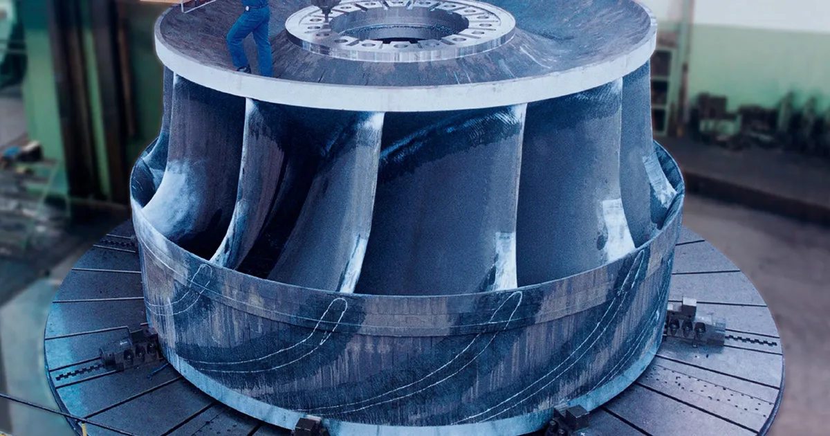
A hydro turbine turns the energy of falling water into rotation, and its efficiency and life depend on how closely the water-contact surfaces follow the design. The parts are large, expensive and made in small numbers. Machining them calls for big machines, long programs and careful inspection.
This guide covers the main components, how they are machined and what a buyer should settle before the casting or forging goes on the machine.
The main components
The runner is the rotating part that the water drives. Francis runners have curved blades between a crown and a band. Kaplan turbines have adjustable propeller-type blades on a hub. Pelton wheels carry spoon-shaped buckets on a disc, for high-head sites.
The head cover, or top cover, closes the top of the turbine casing. It carries bores for the guide vane stems, the seal and bearing area around the shaft and the labyrinth seals.
The bottom ring and the discharge ring form the lower flow boundary and the surface around the runner.
The stay ring and wicket gates guide water into the runner. The gates pivot, and their stems turn in bushings.
The shaft and flange, connecting the runner to the generator, are large forgings with tight tolerances on journals and flange faces.
Material
Runners for Francis and Kaplan turbines are commonly made from martensitic stainless steel with about 13 percent chromium and 4 percent nickel, often CA6NM in casting form or a forged equivalent. It resists cavitation damage and corrosion better than carbon steel. Welded runners fabricate blades and bands separately and join them by welding. Pelton buckets may be cast or forged, in stainless steel or a similar alloy.
Covers and rings are usually made from welded carbon steel or cast steel. The grade, heat treatment and tests come from the turbine designer.
The machining large stainless parts guide describes work hardening and heat in stainless steels, and martensitic grades add the question of the heat treatment condition before machining.
Machining a runner
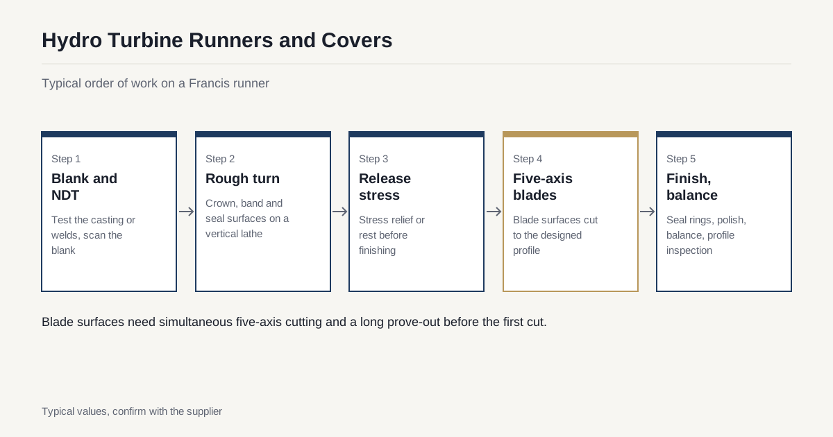
A large runner starts as a casting or a welded assembly with a generous allowance. The machining usually follows this path.
- Check the blank. Non-destructive testing of the casting or the welds, and a scan of the blank to confirm the allowance on the blade surfaces.
- Rough turn the crown, band and seal surfaces on a vertical turning lathe, which holds the runner by its weight on a horizontal table.
- Stress relieve or rest the runner if the process calls for it, because a welded or heavily cut runner moves.
- Machine the blade surfaces on a five-axis gantry or a purpose-built machine, with the cutter following the designed profile blade by blade.
- Finish the seal surfaces and the crown and band faces on the lathe.
- Grind and polish the flow surfaces by hand or with robotic tools to the required roughness.
- Balance and inspect.
The order can vary with the runner type, but the principle is constant. Rough first, release stress, then finish the surfaces that carry accuracy.
The blade surfaces
Blade surfaces are the hardest part of a runner to machine. They are curved in three dimensions, and the water-contact faces must follow the design profile closely, because small deviations change the flow and the efficiency. Cutting them needs simultaneous five-axis motion, long programs and a full machine simulation.
The five-axis machining on large parts guide explains how five-axis work is priced and what it needs, and the CAM prove-out guide explains why the checks come before the cut. For a runner, which is a one-off or a small series, the prove-out is a major part of the job.
A ball-nose or bull-nose cutter leaves scallops between passes. The finish is reduced by finer step-over and by hand or machine grinding and polishing afterwards. The required roughness on flow surfaces is set by the designer.
Seal rings and labyrinths
The runner crown and band carry seal surfaces that form a narrow gap with the fixed parts of the turbine. The gap is small, so the seal surfaces must be round, concentric with the shaft axis and match the head cover and discharge ring. Turning these surfaces on the same lathe and in the same setup as the datum faces keeps them concentric.
Concentricity and roundness are checked with indicators and tracker measurements. The designed gap, often a few tenths of a millimetre, is the guide for the tolerance. Ask the turbine designer for the tolerance, and make sure the shop that machines the runner and the shop that machines the cover know the same gap.
Machining a head cover
A head cover is a large fabricated or cast steel part, flat and round, with a central bore for the shaft and bores around the circumference for the wicket gate stems. The main features are:
- The flange face, which seals to the casing.
- The central bore and seal faces.
- The ring of stem bores, positioned on a pitch circle and relative to the center.
- The facing and bolt holes.
The part goes on a vertical turning lathe or a large boring mill with a rotary table. Because the gate stem bores must line up with bores in the bottom ring, position and concentricity to the main bore matter. The large bore machining and coaxiality guide explains how shops hold bores in line on large parts.
A fabricated cover needs stress relief before finishing, as covered in post-weld heat treatment. Flatness on the large flange face follows the principles in milling large flat surfaces to tight flatness.
A worked example
Take a Francis runner with a diameter of about 3 metres, cast in CA6NM with a generous allowance on the blades. The shop scans the casting before any cut and finds that two blades sit slightly off their nominal position. The programmer shifts the blade toolpaths to share the error and checks that every blade surface keeps at least the minimum stock for finishing.
The runner goes on the vertical turning lathe for the crown and band, then to the five-axis machine for the blades. The program runs for several days in sections, with the shop measuring after each blade to check that the profile matches the model. At the end, the seal surfaces are finished on the lathe in one setup with the datum faces, and the flow surfaces are ground and polished.
The final scan compares the whole blade set with the model and shows a profile deviation map. The report goes to the turbine designer with the balance record. The machining took long because of the blade program and the careful checks, and that time is the main cost of the job rather than the stainless cutting itself.
Inspection
Inspection is a large part of the job.
| What | Typical method | Why it matters |
|---|---|---|
| Blade profile | Templates, large CMM, laser tracker or scan against the model | Hydraulic efficiency |
| Seal surface roundness and diameter | Indicators, tracker, large bore gauges | Seal gap |
| Flange flatness and squareness | Level, tracker | Sealing and alignment |
| Blade spacing and angle | Template or measuring system | Flow and balance |
| Material and welds | Ultrasonic, magnetic particle, penetrant, tests | Structural integrity |
The table lists typical methods, so confirm the actual methods and limits with the turbine designer and the shop.
Agree the profile tolerance and the measurement method before machining starts. The flow surface cannot be measured with a simple gauge, and a poorly chosen method can pass a bad profile or fail a good one. See inspecting large machined parts for how shops plan large inspection jobs.
Balance
A runner turns at speed with a large mass, so unbalance causes vibration that stresses bearings and the generator. Runners are balanced after machining and grinding, often statically on a balancing stand or dynamically on a large balancing machine, to a grade set by the turbine designer. The balancing large rotating parts guide describes when each method is used and what to ask.
Size, weight and handling
Large runners weigh many tonnes and measure several metres across. Handling is a major part of the plan: lifting points, turning the part over, transport to the machine and from it. The machine must carry the weight on its table, and the building must have the crane capacity. See table load and crane capacity for why finished and blank weights both matter, and shipping oversized machined parts for how finished runners and covers travel.
What to put in the RFQ
- Component type, material, specification and heat treatment.
- Blank type, weight and envelope, and who supplies it.
- Drawing and 3D model of the flow surfaces, at one revision.
- Profile tolerance and measurement method.
- Seal surface tolerances and the required gap.
- Surface roughness on flow surfaces and the finishing method.
- Balance grade, if the part rotates.
- Packing and transport requirements.
Closing checklist
- Send the model and drawing at the same revision.
- Agree the profile measurement method before the first cut.
- Ask the shop how it will prove out the blade program.
- Define seal surface tolerances with the matching parts.
- Give the weight and envelope for lifting and shipping.
To start a quote, use the RFQ form and attach the model.
Frequently asked questions
What are hydro turbine runners made of?
Large Francis and Kaplan runners are commonly made from martensitic stainless steel such as CA6NM, cast or welded, because it resists cavitation and corrosion in flowing water. The turbine designer specifies the grade, the heat treatment and the test requirements.
Why is five-axis machining needed on a runner?
The blades are curved in three dimensions, and the water-contact surfaces must follow the designed profile closely. Only simultaneous five-axis motion can cut that form accurately, and it takes long programming and prove-out time.
How is the blade profile checked?
Common methods are templates, a large coordinate measuring system, a laser tracker or a laser scan compared with the model. The method and the profile tolerance must be agreed in advance, since the flow surface cannot be measured with a simple gauge.
Need a quote for a part like this?
Send the drawing with the envelope and finished weight. We match you with up to 3 shops that take parts this size and reply within 24 business hours.
Get matched with a large part shop